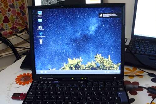
ThinkPad X60 Recovery guide
Contents
Only the Intel GPU is compatible. Do not flash the ATI GPU models.
NOTE: Libreboot standardises on flashprog now, as of 27 January 2024, which is a fork of flashrom. The reason why was explained, in the Libreboot 20240225 release
“Unbricking” means flashing a known-good (working) ROM. The problem: you can’t boot the system, making this difficult. In this situation, external hardware is needed which can flash the SPI chip (where libreboot resides). First, disassemble the machine using the following steps, and refer to the external flashing guide linked later from this guide.
Remove those screws:
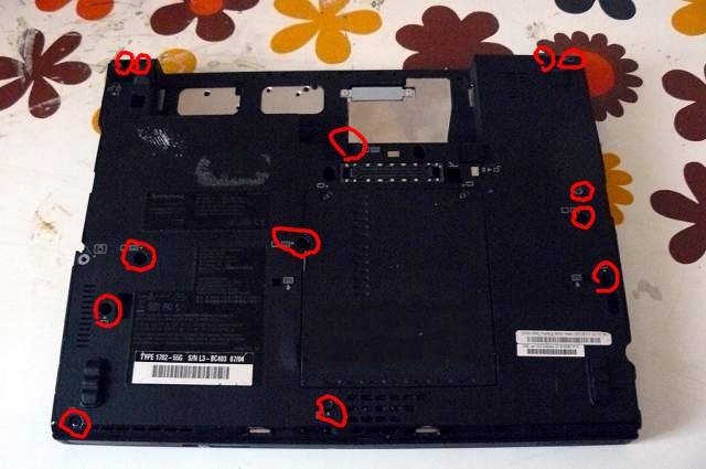
Push the keyboard forward (carefully):

Lift the keyboard up and disconnect it from the board:

Grab the right-hand side of the chassis and force it off (gently) and
pry up the rest of the chassis:

You should now have this:

Disconnect the wifi antenna cables, the modem cable and the speaker:
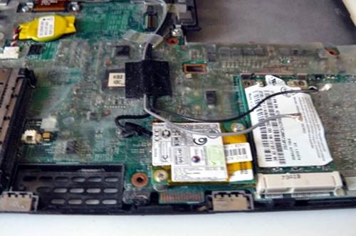
Unroute the cables along their path, carefully lifting the tape that
holds them in place. Then, disconnect the modem cable (other end) and
power connection and unroute all the cables so that they dangle by the
monitor hinge on the right-hand side:
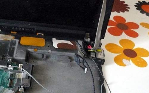
Disconnect the monitor from the motherboard, and unroute the grey
antenna cable, carefully lifting the tape that holds it into place:
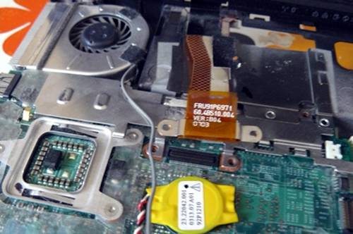
Carefully lift the remaining tape and unroute the left antenna cable so
that it is loose:
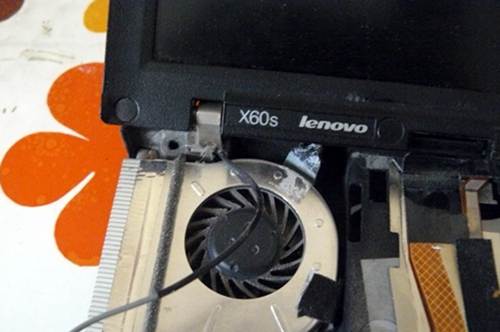
Remove the screw that is highlighted (do NOT remove the other one; it
holds part of the heatsink (other side) into place):
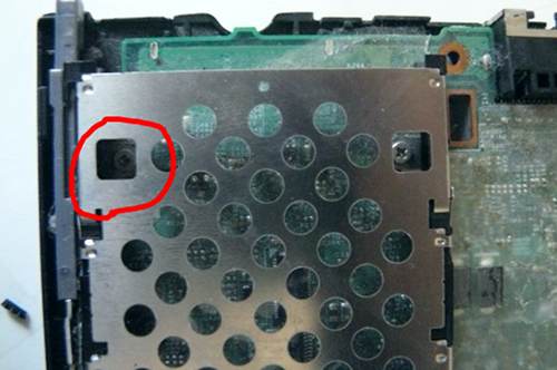
Remove those screws:
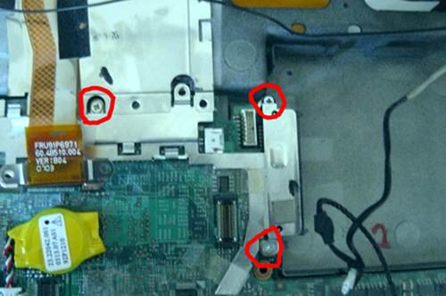
Carefully remove the plate, like so:
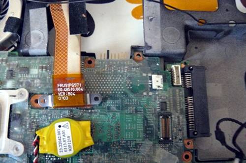
Remove the SATA connector:
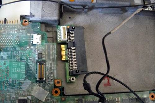
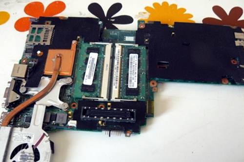
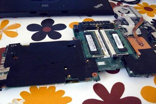
Now remove the motherboard (gently) and cast the lcd/chassis aside:
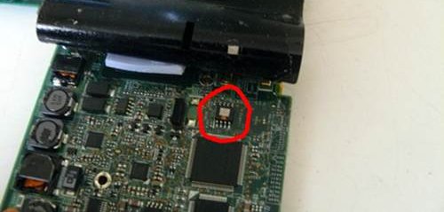
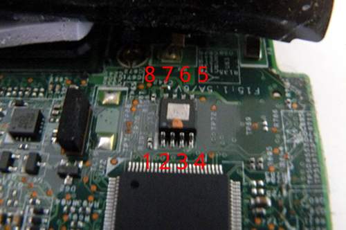
Lift back that tape and hold it with something. Highlighted is the SPI
flash chip:
Here is another photo, with the numbers of the pins written:
 \
\
This photo shows an SPI flasher used, with SOIC8 test clip:
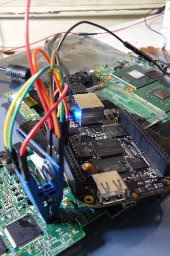
Refer to the following guide:
Externally rewrite 25xx NOR flash via SPI protocol
NOTE: Do not use the 3.3v rail from your raspberry pi. Leave that disconnected. For 3.3v, plug your charger into the mainboard (but do not power on the mainboard) when the clip is connected. Before removing the clip, disconnect the charger. This will provide adequate 3.3v DC at correct current levels. The SPI flash on an X60 shares a common 3.3V rail with many other components on the mainboard, which all draw a lot of current, more than your programmer can provide.
When you’re finished flashing, remove the programmer and put it away somewhere.
Put back the tape and press firmly over it:
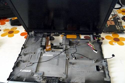
Your empty chassis:
Put the motherboard back in:
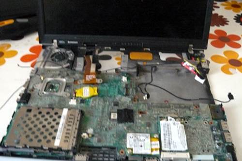
Reconnect SATA:
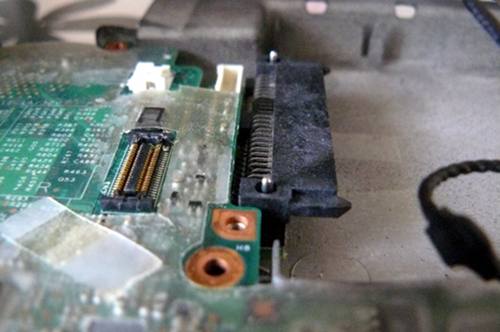
Put the plate back and re-insert those screws:
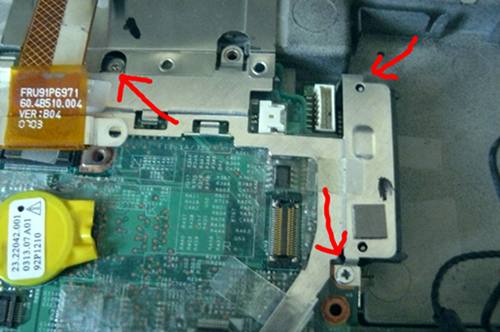
Re-route that antenna cable around the fan and apply the tape:
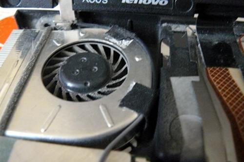
Route the cable here and then (not shown, due to error on my part)
reconnect the monitor cable to the motherboard and re-insert the
screws:
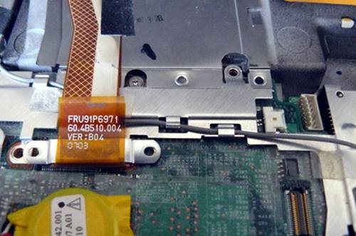
Re-insert that screw:
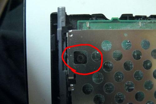
Route the black antenna cable like so:
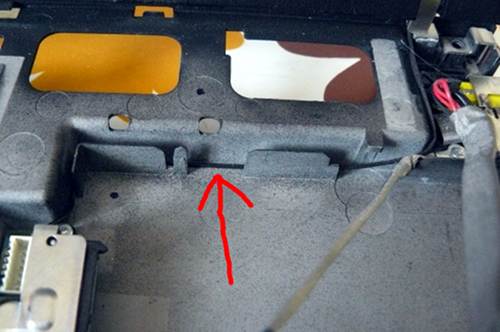
Tuck it in neatly like so:
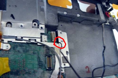
Route the modem cable like so:
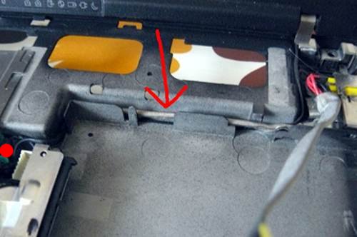
Connect modem cable to board and tuck it in neatly like so:
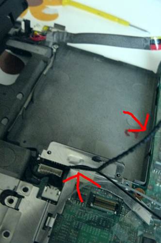
Route the power connection and connect it to the board like so:
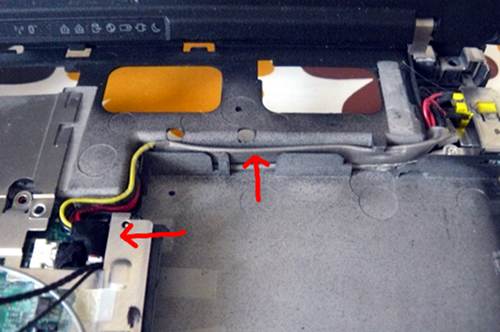
Route the antenna and modem cables neatly like so:
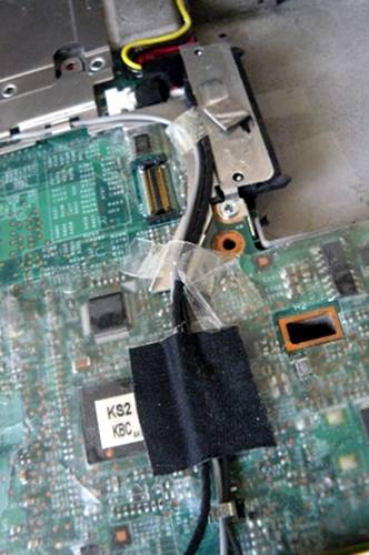
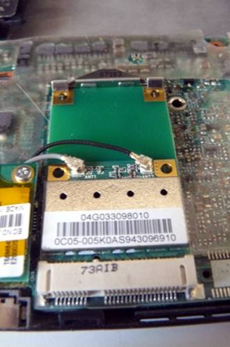
Connect the wifi antenna cables. At the start of the tutorial, this
system had an Intel wifi chip. Here you see I’ve replaced it with an
Atheros AR5B95 (supports 802.11n and can be used without blobs):
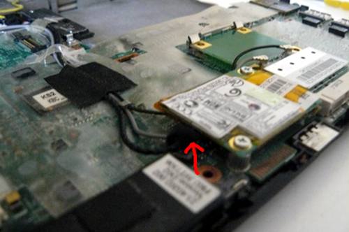
Connect the modem cable:
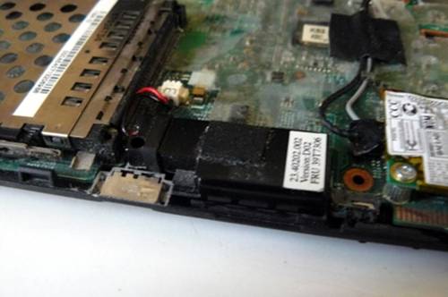
Connect the speaker:
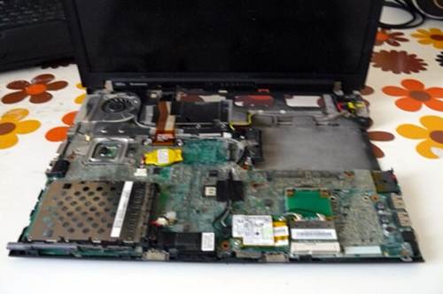
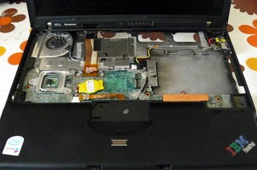
You should now have this:
Re-connect the upper chassis:
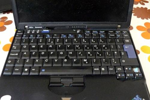
Re-connect the keyboard:
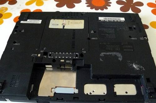
Re-insert the screws that you removed earlier:
Power on!
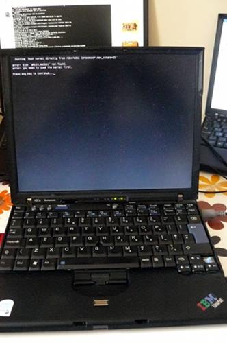
Operating system:
